W0VFW Antenna Work Day

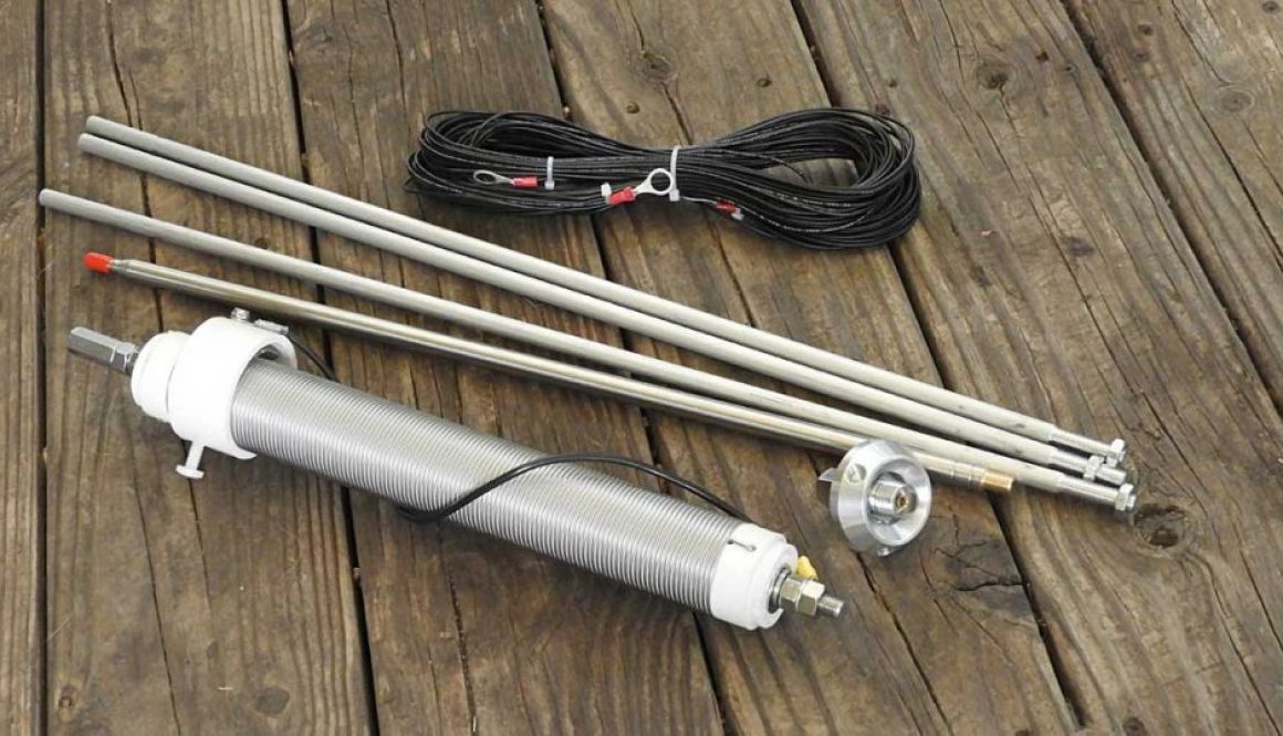
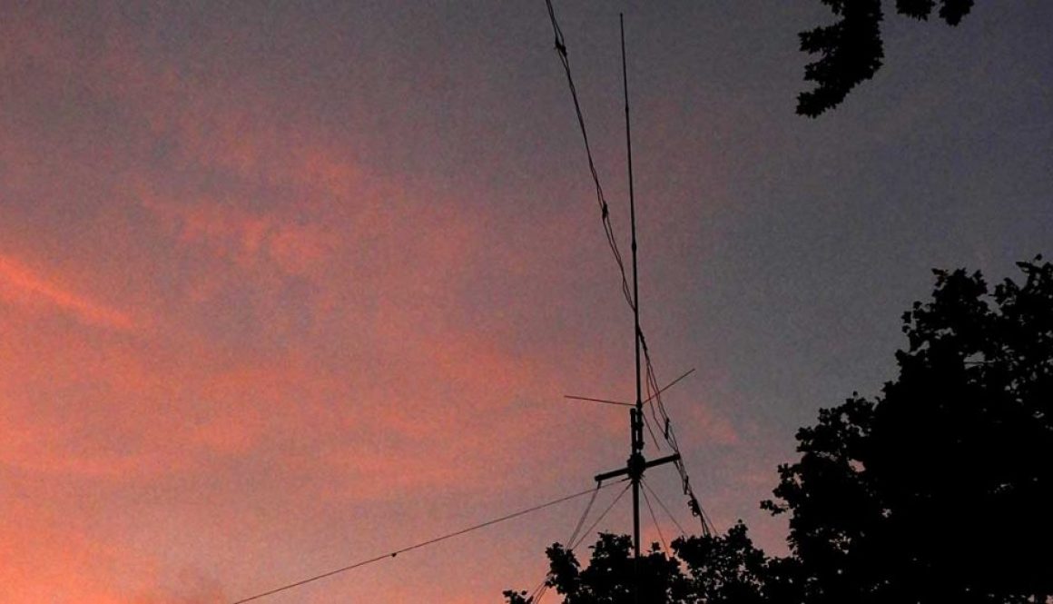
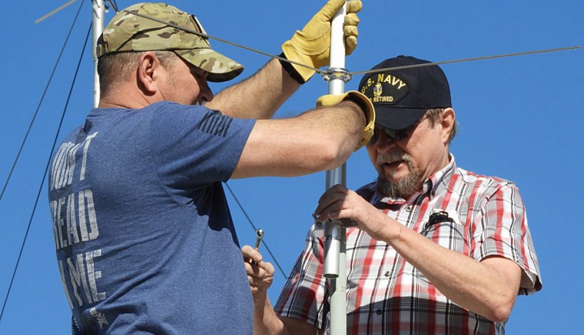
Members of the W0VFW ham club and 52 Crew members gathered to install a new GP9 antenna atop the VFW Post 3115.


Antennas / 2 meter antenna, W0VFW / 0 comments
Members of the W0VFW ham club and 52 Crew members gathered to install a new GP9 antenna atop the VFW Post 3115.
Antennas / antenna mast, EMCOMM, emergency antenna, fiberglass antenna poles, field day, portable antenna / 2 comments
For this 2019 Field Day project, I wanted to build a 40 Meter inverted V dipole antenna that could be easily deployed in the field.
It was designed and tuned for a target frequency of 7.237 Mhz.
Using the formula 468 / 7.237=64.66 total length. I added 4′ for connection winds and a little slack that could be trimmed during tuning if necessary.
My research into antenna making led me to many people that promoted using inexpensive small gauge steel electric fence wire for the antenna elements. I chose not to go that route and instead used Southwire 55667123 Primary Wire, 14-Gauge, Black insulated wire for the antenna elements (each leg 33.5′). That wire is much easier to handle with fewer twists and kinks.
What I wanted was something simple and low cost I could use for a center insulator. There were numerous commercial insulators like those from MFJ available as well as lots of examples of build-it-yourself PVC designs. All were quite interesting, but then I discovered something I hadn’t seen before. What I found was the Budwig HQ-1 Center Insulator with SO-239 UHF Female Connector and two ceramic dogbone insulators for about $20. Simple and relatively low cost.
I bent the ends of the insulator at an angle approximating the angle for the two end connections. I next soldered each antenna element to the insulator. To keep it waterproofed, I wrapped the connections with X-Treme Tape TPE-XR1510ZLB Silicone Rubber Self Fusing Tape.
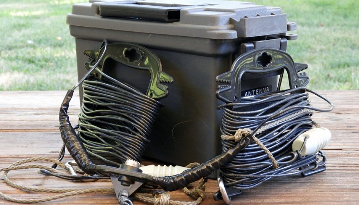
Now I had a lightweight portable antenna that easily wound onto two hand spools and fit neatly inside a Harbor Freight Ammo Box. Total cost of less than $40.
I deployed the antenna in my back yard in a less than desirable situation to get the antenna tuned to my target frequency and practice setting up on a fiberglass pole mast. After a few minutes with the MFJ-Analyzer, I trimmed a few inches off the end and had the antenna resonate at my desired frequency. I ended up with each leg being 32.5′. Took it down and packed it away for Field Day.
I planned on joining the Flint Hills Amateur Radio Club group for Field Day on Saturday and overnight until Sunday. This was to be my first time deploying the Military style fiberglass poles in a real world environment in the field. To elevate the center of the antenna to 32′ required 8 poles and another three for the tri-pod base. 6 more poles were used for the two supports for the ends of the antenna.
On Friday night before Field Day, the club cancelled the outdoor event because we were expecting severe weather on Sat/Sun. However we were still invited out Saturday for a cookout of the food already purchased before the storms rolled in. Since I already packed my Jeep for Field Day, I joined the group late Saturday morning. Barb (KD0WAU) and Wayne (KD0WAT) had already put up an antenna for their radio so I said, “What the heck.” I had planned for this event for months and decided to take advantage of the presently calm weather.
Several others joined in to help me put up my antenna and in no time I was on the air. I made several contacts and a couple other people made a few contacts each.
The farthest contact made from my station was 541 miles into Texas. Had quite a few contacts in Texas and others in Missouri, Nebraska, Iowa, and Illinois. This setup seemed to work great for regional contacts.
By mid-afternoon the clouds began rolling in and bad weather threatened so everyone decided to shut down and head home. While it was a shortened Field Day, I did accomplish my goals to deploy in the field using only battery power to make contacts.
I considered this Field Day a “success” since I was able to successfully deploy my antenna and operate my IC-7300 off a 12-volt battery.
Antennas / antenna mast, fiberglass antenna poles, military surplus fiberglass antenna mast, military surplus fiberglass antenna poles / 0 comments
I found what I believe to be a great solution for a portable antenna mast that can be used for EmComm purposes, field day, or even a temporary antenna deployment at home.
I picked up this combo from BJB Farms at a recent ham fest in Wichita. It’s made up with 48″ surplus military fiberglass camo netting poles and a special tripod adapter for connecting it all together. This combo I purchased included poles for getting an antenna 32 ft. high, all stored inside a military carrying bag.
The tripod base is made from fiberglass poles and a tripod adapter. I can use 3 legs for a simple tripod base and top-load the fiberglass poles or double stack 6 poles to raise the center point of the tripod higher and bottom feed the fiberglass poles. When bottom feeding, you will need poles that have the reinforced fiberglass collars that come with many fiberglass poles removed to fit inside the middle of the tripod. The tripod can then be tied down or strapped down using stakes. When using on pavement it can be weighed down using weights or sand bags.
In addition, I can use the guy plates placed between any of the 4 ft. section of poles. I plan to guy it at the 16 ft. and 32 ft. levels. Also, there is a base stand at the bottom of the center pole section that can be anchored with stakes or weights to keep the tower stable and straight.
At the heart of this setup is the tripod that allows you to lock the legs so they don’t fall out while setting up. The inside diameter for the middle of the tripod is 1.8 inches; the legs are 1-3/4 inches to fit military fiberglass and aluminum poles only. If your poles have a ring on the bottom of it you will first need to cut the ring off in order to get the pole into the tripod and/or base. The tripod weighs almost 5 lbs.
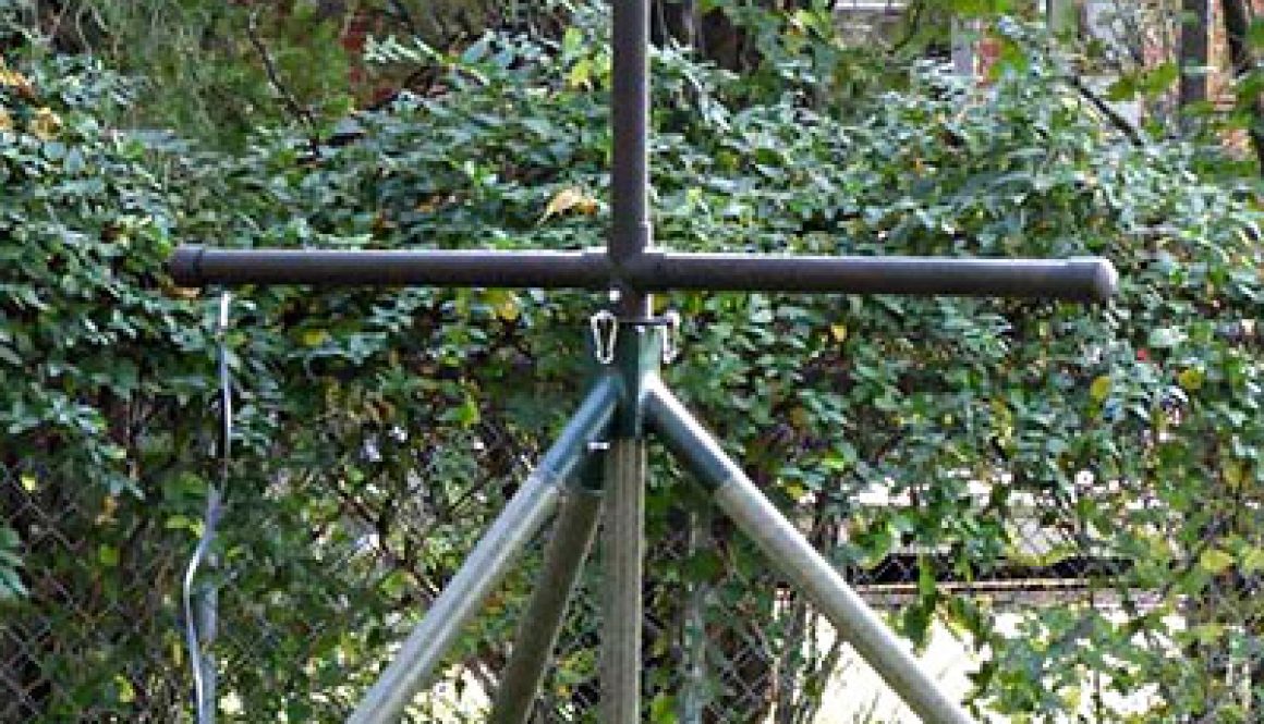
I fashioned a top section for the mast out of PVC to hang either an HF wire antenna or my 2 meter roll-up j-pole. There is also a vertical section that will allow me to attach a vertical antenna. The assembly is made up of 3 sections of 1 1/2″ PVC connected at the center with a 4-way adapter that neatly slips on the male end of the fiberglass pole. To secure the top section to the center pole and keep it from moving around in the wind, I inserted a bolt with wing nut through the 4-way adapter and top section of pole. At the two ends of the horizontal sections I put eye hooks to suspend my antennas. I also put on the ends of the PVC pipe end caps to keep the moisture out of the inside of the poles and finished it off by painting the assembly a non-reflective camouflage color.
Set up and tear down takes only a few minutes and everything fits inside the carry bag making this antenna mast portable and simple to deploy.
It’s simple enough for one person to put up a 16′ mast, but pushing it up vertically gets pretty heavy and the top of the mast gets pretty wonky above the 24′-28′ level. If you’re thinking of putting the sections together and walking it up, that’s probably NOT a good idea for anything higher than 16 or 20 feet. It’s possible to damage the joints if to much bending motion is put on the fiberglass joints and they can split. Instead, with guy ropes attached to the top section and anchors, stand up the first three or four sections and let the mast lean against 2 of the guys to hold it up. Then pick the mast up vertically while keeping it leaning against the guy ropes and slip the next section in underneath. Set it back down while you grab the next section. Having assistants holding the guys to keep them tensioned while raising can be helpful, but with practice one person can do it.
The one down-side I see with this tripod antenna mast is that it needs to be deployed on level ground. I am investigating a method to shim up one or two legs of the base to allow for a level placement on uneven ground. Also, I’m looking into a method to attach spikes or something to attach to the ends of the three legs to even better secure the mast to the ground.
Antennas / 2 meter antenna, delta loop, emergency antenna, portable antenna, VHF / 2 comments
Springtime in Kansas brings more than just flowers… it also brings those nasty spring thunderstorms, dangerous lightning, and sometimes accompanied by tornadoes. Since I would be disconnecting my outdoor antenna during those severe thunderstorms, I wanted some kind of alternative antenna I could use to monitor local ham frequencies… keeping in touch with storm spotters and perhaps more.
I’m testing three alternatives at this point.
1 – A 2 meter mag mount antenna on a 20″ pizza pan for a ground-plane.
2 – Roll up J-Pole/Slim Jim antenna
3. A home brew DIY Delta Loop antenna
It’s the construction of the Delta Loop antenna that is the subject of this post. I found an interesting project from Gordon Hoag (K2ZS) at K2ZS.com that I thought to model my antenna after. I thought I would build a PVC pipe frame to support my antenna and make it somewhat portable but after building a prototype, I abandoned that idea. It was just too unwieldy and not all that portable.
Since I wanted to monitor 2 meter repeater and simplex frequencies, I chose my target frequency to be 146.52 Mhz – the national calling frequency and the frequency used by many hams in my area. I also wanted good SWR at 146.85 Mhz as that was the frequency for one of the more popular repeaters used by storm spotters in the area.
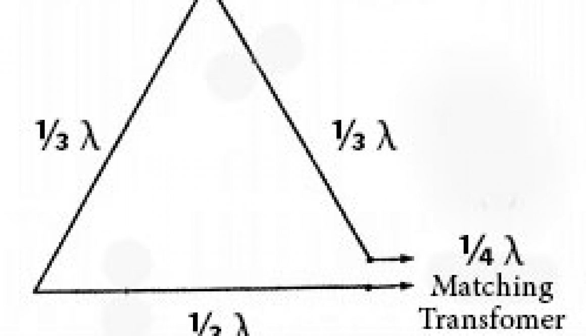
Delta loops require a full wavelength of wire (1005/frequency = feet or , for instance 1005/146.52 = 6.859) or approximately 6′ 10 7/8″ gives me the length of the entire wire. Since I will be building a 3-sided delta loop, I divide that 6.859 / 3 = 2.29 feet or about 27 1/2″ per side.
Since I would be tuning the antenna later by either lengthening or shortening it, I decided to start with a bit longer wire for the lowest frequency in the 2 meter band. I figured it’s easier to shorten a wire rather than lengthen it so I started with a wire of the longest length. So I cut my first wire for 144.00 Mhz and split that into three separate pieces (27 7/8″) for each side of my triangle shaped antenna.
Like in the K2ZS model, I planned on using dog bone insulators for my corners and shorting wires on the top and one side to connect all three wires together.
The wire I chose for my antenna was 14 AWG stranded THHN wire that I purchased from a local home improvement store.
Since I wanted to use this antenna for FM simplex and repeaters it would need to be vertically polarized. To do that, it would need the feed point in the bottom corner. The feed point impedance of a delta loop will range from 70 ohms to 100 ohms so I would need to adjust for that matching to 50 ohms for the radio.
Instead of using a 4:1 balun, I’ll be using a matching section of 75 ohm coax for my Q-Match. I’ll need a quarter wavelength matching transformer that is 1/4 wavelength of 75 ohm coax (RG-59U) multiplied by .67 to compensate for the velocity factor of the 75 ohm cable. Using the formula 246*.67/f (146.52) gave me a quarter wavelength of 1.12 ft.
After putting everything together, it was time to connect my MFJ-259C antenna analyzer and tune this antenna to be resonate at 146.85 Mhz.
I would take a analyzer reading and shorten the wire to raise the frequency or lengthen the wire to lower the frequency. After many adjustments I became pretty frustrated because I could get it resonate around 130.00 MHZ or around 151.00 Mhz, but after numerous trials could not get even close to 146.52.
Next I experimented with just feeding the antenna with a single length of RG-59U coax without the matching stub. I also tried 8 turns in coax about 4″ in diameter for a balun. No luck.
So, it was back to the drawing board and I decided to use a single length of wire instead of three separate pieces connected with the shorting wires. I also abandoned the PVC pipe frame and built the antenna to be hung almost anywhere.
Suspecting a problem with either the 1/4 wave stub or the feed line, I rebuilt the matching stub after visiting the coax manufacturer’s website, finding the specifications for the coax, and found a more precise velocity factor for the coax I was using. Using that new velocity factor (.78), I remeasured and cut my new stub to the resulting length… 246*.78/f (146.52) = 1.31 ft.
Again, using dog bone insulators for two of my ends, I simply threaded the wire through one hole of the insulator and a piece of string through the other hole to tie off at the top and bottom. I also devised a feed point bracket out of a cut in half piece of PVC pipe that allowed me to tie off the two ends of the antenna wire and another point to tie off that end to it’s support. I soldered alligator clips to my matching stub so I could move the connection points on the antenna to lengthen or shorten.
Using my antenna analyzer and numerous adjustments, I was able to get the antenna resonate at 146.52 Mhz. with an SWR of 1.1:1.
I attached the matching stub to a length of 50 ohm coax running to my 2 meter radio and went on the air to test. I was able to work most of the local contacts I’m familiar with. They reported my signal was good and audio good, but with a little static. My reception was also fairly good with some static not present on my outdoor 2 meter Tram 1280 antenna. I also did a quick comparison with my mag mount antenna on a pizza pan and my roll-up J-Pole/Slim Jim antenna hanging from the ceiling in my shack. The delta loop outperformed both of those with better reception and better reported signals. There were a couple more distant stations I couldn’t reach with the delta loop antenna, but felt it was a success for an emergency antenna.
To put the finishing touch to my new home built delta loop 2 meter antenna, I soldered the matching stub to the ends of the antenna, cut some lengths of bunjee cord instead of string to tie off the ends, and beefed up the connection point bracket to withstand a little abuse when moving the antenna around.
All in all, this first DIY antenna project was a success in more ways than one. Besides giving me an alternative antenna to use when severe weather threatens, it can also make a good portable antenna that easily fits inside my go bag. I learned allot of lessons during this project and also several techniques for cutting wire, soldering, etc. I was also introduced to Smith Charts, although I’ve got to admit I still don’t really know how to use and interpret them. Perhaps they’ll come in again when I tackle my next DIY antenna project.